
©2015 -


Information Technology


Oracle Grid Cluster Installation With NFS
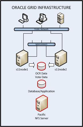
The Oracle Grid (introduced in Oracle 10g Database release back in 2003) is a product part of the Oracle database installer. It provides the clusterware and the storage manager (ASM, Automatic Storage Manager) that is essential for the Oracle RAC database.
As depicted on the diagram, there are two network segments, one is for the public network where most users and applications are connected, and the other is a private network which is meant for cluster communications.
The OCR data (Oracle Cluster Registry) is a repository of registered resources (database, listeners, applications). The vote data is a small file which contains the keys when casting a vote by each node during cluster panic such as a split brain. Another shared repository which either belongs to a database or an application is presented in the diagram to denote that an application can be made available on both nodes for high availability purposes. Both the Grid data and the optional Database/Application data are stored and presented by an NFS server.
When configuring the Grid, you have the option to either use the ASM storage or Shared Storage (Cluster File System or NFS) to store the registered resource data and voting data.
In this exercise, we will demonstrate the use of NFS which is a very common shared file system in the UNIX world but rarely used by DBAs since little is known of its function. At the same time, we will have the chance to examine the steps to build an Oracle Grid cluster. We will be using VMware Fusion running in Mac OS X to simulate our server environment.
Table Of Contents
High Level Summary of Requirements
Network Interface Setup (VMware)
Configure Permanent Private IP
Environment Variables and Required Directories
Setup SSH Key Authentication For Grid User
Application Resource Configuration
Adding An Application VIP Resource In The Cluster
Check The Status Of The Grid Cluster
Dropping An Existing VIP For Use With Cluster
Add A Network Resource To The Grid Cluster
Grant Run/Exec Permissions To Grid User To Manage Network Resource
Adding An Application Control Script Resource
Sample For Building The Control Script For Runtime Start/Stop
Add Control Script As Resource In The Cluster
Basic Cluster Management
HIGH LEVEL SUMMARY OF REQUIREMENTS
- An NFS Server preferably running on Solaris platform for better performance and stability.
I have the following setup,
Host: pacific
OS: Solaris 10 x86-
RAM: 3 gb minimum
Shared Disk mount: 2 gb minimum
Description: This host is for the NFS shared directories for Oracle Grid.
- At least 2 server hosts for the cluster. In my case I have 2 VM hosts running in Mac OS X.
Host: s11node1, s11node1.vlabs.net
OS: Solaris 11.2 x86-
RAM: 6 gb
Disk: 35 gb
Additional Net Interface:
eth1 (for the interconnect)
Description: This host is the primary node of the cluster
Host: s11node2, s11node2.vlabs.net
OS: Solaris 11.2 x86-
RAM: 6 gb
Disk: 35 gb
Additional Net Interface:
eth1 (for the interconnect)
Description: This host is the failover node of the cluster
- IPs for the clusterware for a 2-
node configuration
- An additional network interface for the private IP for the clusterware interconnect (heartbeat and cluster data). The private IPs must be pre-
configured. - 1 node-
VIP for each cluster member - At least 1 SCAN IP.
- Setup Oracle Grid user.
- Setup NFS Client mount as Shared Storage for the Grid clusterware.
- An Oracle 11g Grid installer.
A good reference for the pre-
http://docs.oracle.com/cd/E11882_01/install.112/e47805/presolar.htm#CWSOL165
NETWORK INTERFACE SETUP (VMWare Fusion)
ADD NETWORK INTERFACES FOR CLUSTERWARE INTERCONNECT ON BOTH NODES -
1. Shutdown the VM instances (s11node1 and S11node2).
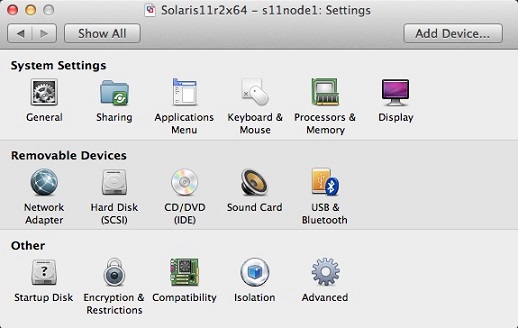
2. At the VMWare Fusion menu, launch the Virtual Machine Library and select the node you'd like to add a network interface then click on the settings. The Settings window will then appear.
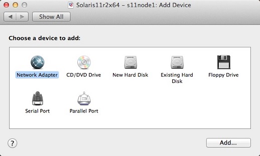
3. Click "Add Device..." from the Settings window and select "Network Adapter" and click [Add..] button.
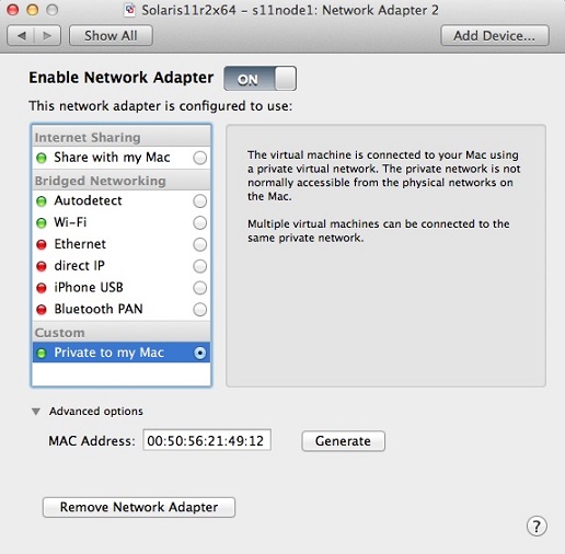
4. At the Network Adapter 2 window, select network configuration as "Private to my Mac" (make sure that the radio button is marked and not just highlighted), then expand "Advanced options" and click [Generate] MAC Address then take note of the new mac address. This will be the MAC address to configure the IP for use with oracle Clusterware interconnect.
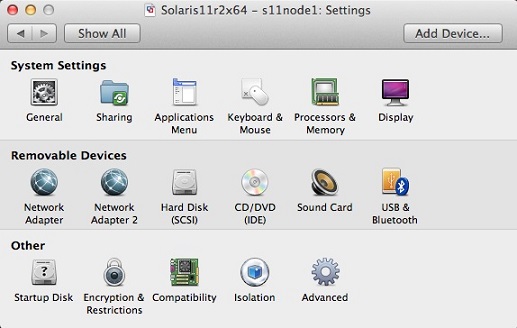
5. Click the [Show All] button, the settings window should now reflect Network Adapter 2.
Repeat the above procedures for the second node s11node2.
CONFIGURE PERMANENT PRIVATE IP ON THE NEWLY ADDED NETWORK INTERFACE
1. Check the interface at the host and look for the MAC address we previously noted of the Network Adapter 2 to see if the OS had recognized it.
Example:
chad@s11node1:~$ dladm show-
LINK MEDIA STATE SPEED DUPLEX DEVICE
net0 Ethernet up 1000 full e1000g0
net1 Ethernet up 1000 full e1000g1
chad@s11node1:~$ dladm show-
LINK SLOT ADDRESS INUSE CLIENT
net0 primary 0:c:29:1b:7a:7b yes net0
net1 primary 0:50:56:21:49:12 yes net1
chad@s11node1:~$
Based on the results above, the new interface is on Link net1 of Device e1000g1.
2. Check the IP assignment of the network link and create a permanent IP.
Example:
chad@s11node1:~$ ifconfig net1
net1: flags=100001004843<UP,BROADCAST,RUNNING,MULTICAST,DHCP,IPv4,PHYSRUNNING> mtu 1500 index 3
inet 192.168.65.129 netmask ffffff00 broadcast 192.168.65.255
chad@s11node1:~$
The result above tells us that the IP was generated dynamically via DHCP. Since this IP is randomly generated, we needed a more permanent one for consistency when assigning a hostname for use with our cluster interconnect.
Reconfigure the VMware to use static DHCP IP for the MAC address of the newly added network interface. If you don't know how to do this, read my article -
I had used the following template for the static IP:
HOST PRIVATE HOST LINK MAC IP
s11node1 s11grid1 net1 0:50:56:21:49:12 192.168.65.111
s11node2 s11grid2 net1 00:50:56:3B:3D:9B 192.168.65.112
Once done on reconfiguring the newly added network interface, startup the VM instance and check again if our changes has taken effect.
Example:
chad@s11node1:~$ cat /etc/resolv.conf
#
# _AUTOGENERATED_FROM_SMF_V1_
#
# WARNING: THIS FILE GENERATED FROM SMF DATA.
# DO NOT EDIT THIS FILE. EDITS WILL BE LOST.
# See resolv.conf(4) for details.
domain vlabs.net private.net
nameserver 172.16.33.2
nameserver 192.168.65.1
chad@s11node1:~$
chad@s11node1:~$ ifconfig net1
net1: flags=100001004843<UP,BROADCAST,RUNNING,MULTICAST,DHCP,IPv4,PHYSRUNNING> mtu 1500 index 3
inet 192.168.65.111 netmask ffffff00 broadcast 192.168.65.255
chad@s11node1:~$
Modify /etc/hosts on both s11node1 and s11node2 to add entries for the host assignment of the private IPs. The entries should be something like this:
#
# Copyright 2009 Sun Microsystems, Inc. All rights reserved.
# Use is subject to license terms.
#
# Internet host table
#
::1 s11node1 localhost
127.0.0.1 localhost loghost
172.16.33.120 s11node1 s11node1.vlabs.net
172.16.33.121 s11node2 s11node2.vlabs.net
172.16.33.126 pacific pacific.vlabs.net
192.168.65.111 s11grid1 s11grid1.private.net
192.168.65.112 s11grid2 s11grid2.private.net
172.16.33.99 oem-
Test if a ping is successful between the private IPs using the assigned host names.
example:
chad@s11node2:~$ ping s11grid1.private.net
s11grid1.private.net is alive
chad@s11node2:~$
chad@s11node1:~$ ping s11grid2.private.net
s11grid2.private.net is alive
chad@s11node1:~$
So far what we had on the network interfaces are the Public node IP (which is the host), the Private node IP for the interconnect (configured on both nodes) and the application OEM VIP which is currently configured at s11node1.
The Oracle Grid clusterware needs a Public VIP for each node and a SCAN IP.
Oracle had suggested to name the public node vip in the format of hostname-
Create Virtual Node IPs
This is supposedly the rac-
172.16.33.118 s11node1-
172.16.33.119 s11node2-
Create SCAN IPs
Even though on certain applications we don't need SCAN IP which is an IP supposedly configured at the DNS to load balance across multiple public IPs meant for Oracle RAC listeners, but it is necessary that we at least configure one even if we don't use it since this is something we can’t skip in a grid configuration.
In the absence of DNS, I will configure a Scan IP host on each node that will point only to a single IP which is the minimum allowed by Oracle.
172.12.33.100 s11node-
A Note From Oracle doc -
"Because of the Oracle Clusterware installation requirement that you provide a SCAN name during installation, if you resolved at least one IP address using the server /etc/hosts file to bypass the installation requirement but you do not have the infrastructure required for SCAN, then, after the installation, you can ignore the SCAN and connect to the databases in the cluster using VIPs.
Oracle does not support removing the SCAN address."
Both the Virtual RAC node IPs and the SCAN IP should not be configured on any NIC. It's the Clusterware that takes care of this.
Your final /etc/hosts for both s11node1 and s11node2 should look something like this:
127.0.0.1 localhost loghost
172.16.33.120 s11node1 s11node1.vlabs.net
172.16.33.121 s11node2 s11node2.vlabs.net
172.16.33.126 pacific pacific.vlabs.net
192.168.65.111 s11grid1 s11grid1.private.net
192.168.65.112 s11grid2 s11grid2.private.net
172.16.33.99 oem-
# node VIPs
172.16.33.118 s11node1-
172.16.33.119 s11node2-
# SCAN IP
172.12.33.100 s11node-